1992 → 1996[]
Left engine mount[]
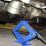
- Set parking brake. I raised my van and placed on jackstands for some other work, but this shouldn't be necessary.
- Support the engine with jack and a piece of 2X4. I did this under the oil pan. You aren’t lifting the van with the jack… so the pan won't be damaged.
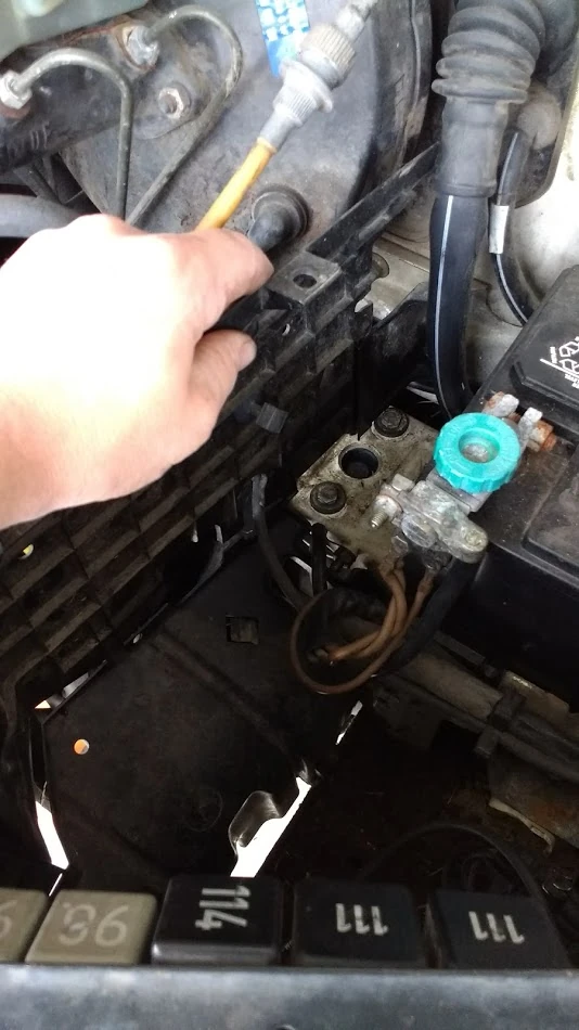
- Remove plastic trim piece to left of battery (image 1).

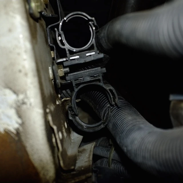
- Use Philips screwdriver to remove radiator hose from bracket. Maybe you don’t even need to do this, but I did.
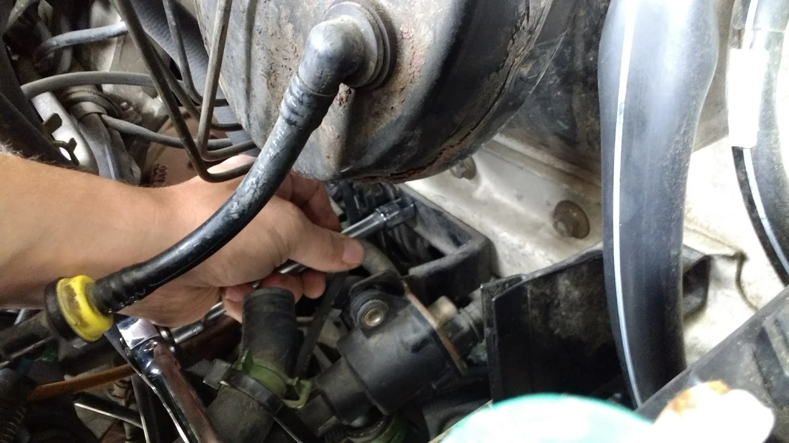
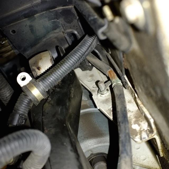
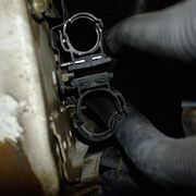
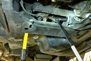
- Remove bracket from firewall holding radiator hose with 10mm socket… otherwise it gets in the way when you try and remove the motor mount (image 2).

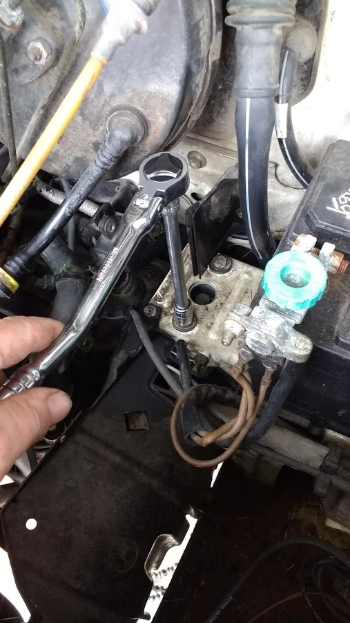
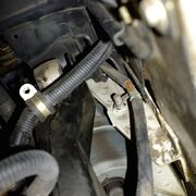
- I loosened the large, center bolt first (5/8 fit better than 16mm socket) and then the two smaller ones (13mm). I carefully removed the smaller ones then slowly removed the larger one. The engine moved very little or not at all when bolt is removed. The jack held everything in place nicely (image 3).
- The mount was removed by just shifting/sliding it to the left. I thought I'd have to lower the engine a bit to remove pressure from the mount, but it just slid right out. I then shifted in the new mount and rebolted. I lightly tapped the mount through the larger hole with the driver extension (use anything) to center it before final tightening.
1997 →[]
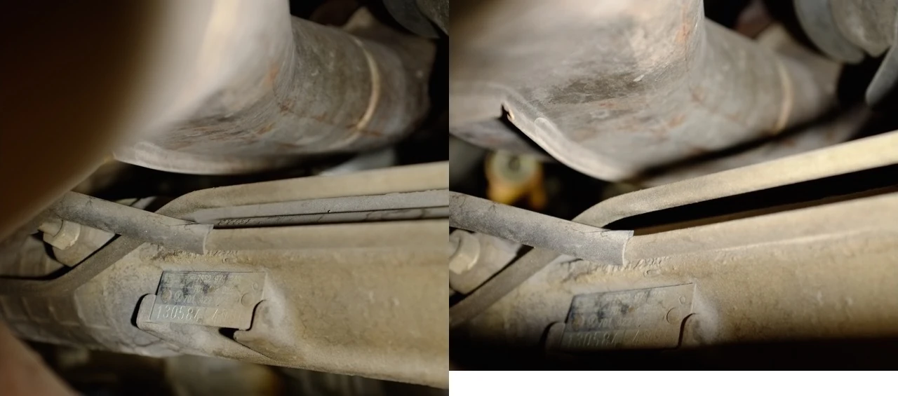
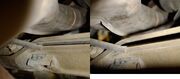
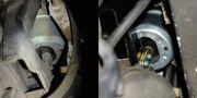
Before (left) and after shots showing proximity of the exhaust downpipe to the power steering lines on the steering rack. This fails to show the difference well because of photographer ineptitude. Note that there is a gap shown between the rack and the line on the after shot but not on the before shot. That is because the shots were not taken at precisely the same angle. Trust me, though, the downpipe clearance is improved after engine mount replacement.

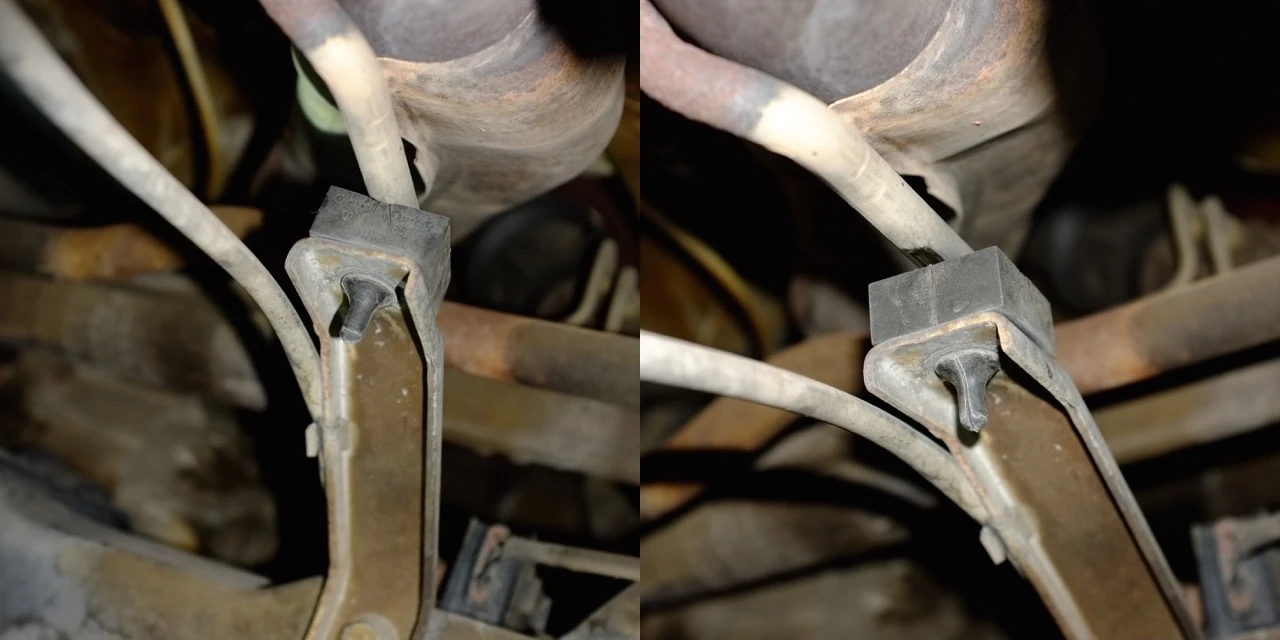
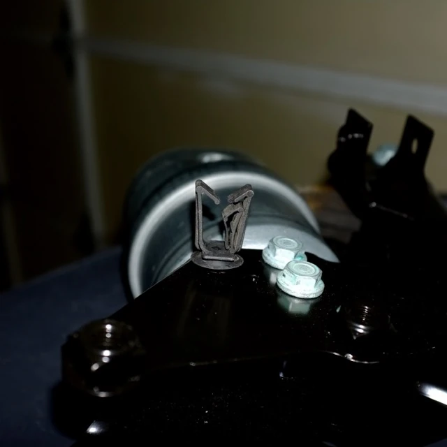
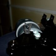
Before (left) and after shot of exhaust pipe snubber. After mount replacement, the exhaust pipe brace lifts off of the snubber slightly.
Right engine mount[]

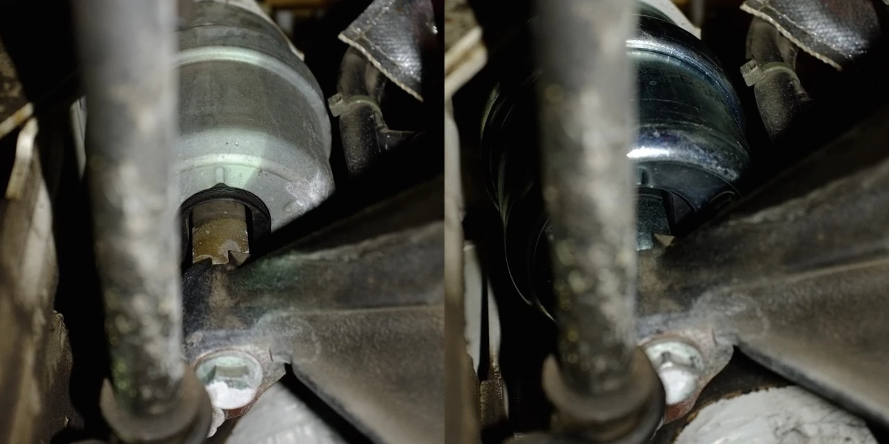
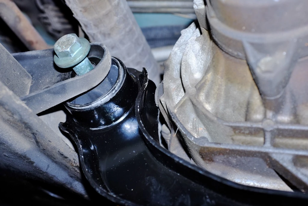
Before (left) and after shot of right engine mount. Note that in the old saggy engine mount, the rubber bits inside are bottomed out on the inside of the metal can. It's hard to see, but on the new mount, even under the full weight of the power plant, the rubber bits maintain their recessed position inside the can.
There's a video of a worn right engine mount here.
- Set the parking brake.
- Remove the cabin air intake and filter.
- Support the engine with a jack and enough pieces of wood to distribute the weight.
- The two nuts on top of the mount and one bolt on the bottom are 16mm.
- Remove the old mount.
- The bottom of the mount has a ridge on it that needs to be resting in a matching channel. While screwing in the bottom bolt, the whole mount will twist causing the ridge and the channel to misalign. Screw in the bottom bolt until the ridge is about to meet the channel. Then, put a socket over each of the loose top nuts and tap them until the ridge and channel align. Tighten the top nuts to hold that alignment and then continue screwing in the bottom bolt to seat the ridge into the channel.
Left engine/transmission mount[]
The power plant is designed such that the transmission is attached to the left of the engine, so this mount is technically a transmission mount. The Bentley manual refers to this as the 'Modified Transmission Mount'.
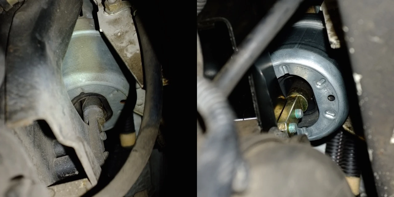
Before (left) and after shot of the left engine/transmission mount. Note that in the old saggy mount, the rubber bits are bottomed out on the inside of the metal can. On the new mount, even under the full weight of the power plant, the rubber bits maintain their recessed position inside the can.

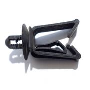
Wire harness clip on side of left engine/transmission mount.
Location of clip on left mount.)

For the left mount, this flat spot on the transmission can be used for supporting the power plant with a jack.
Disconnect cables for ease of access.)
Removing this cable restraint might be necessary in order to get enough clearance for an 'extra long' wrench.
- Set the parking brake.
- Remove the top of the battery box.
- Remove the side of the battery box. It just slides straight up.
- Disconnect the battery.
- Disconnect ground and positive cables shown in photo.
- Disconnect the positive cable from the starter solenoid.
- To gain room to swing an extra large wrench, it may be necessary to remove the cable retainer show in the photos from the front end of the frame rail.
- A small wire harness clip presses into the side of the mount bracket, on the engine side. If you have small hands and arms you can pull out this clip before removing the mount and reinstall it after installing the new mount. See photos.
- A flat spot on the bottom front of the transmission can be used for jacking See photo.
- Support the transmission with the jack.
- The two top nuts and two side bolts are all 16mm.
- When the nuts and bolts have been removed from the mount and its bracket, the whole assembly can be rotated forward and then dropped out of the engine compartment.
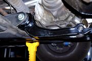
Pendulum Mount[]
A large rubber damper sits within a bushing in the aft end of the so-called Pendulum Mount that stops the bottom of the power plant from swinging forward and aft as it hangs from the left and right mounts at the top of the power plant.
There is a video here of a worn mount that illustrates the excessive movement it causes. A similar video is here.
The bolt on the transmission requires a 10 mm hex key. The bolt on the frame requires a 21 mm socket. Torque specs can be found on panel J 37-37 of the Bentley manual.

This shows a wrench on the point where the Pendulum Mount attaches to the transmission.
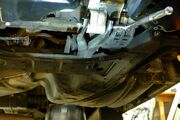
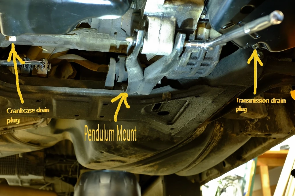
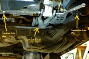
This shows a couple of labeled landmarks that should help to locate the Pendulum Mount.

This shows a wrench on the point where the Pendulum Mount attaches to the sub-frame.


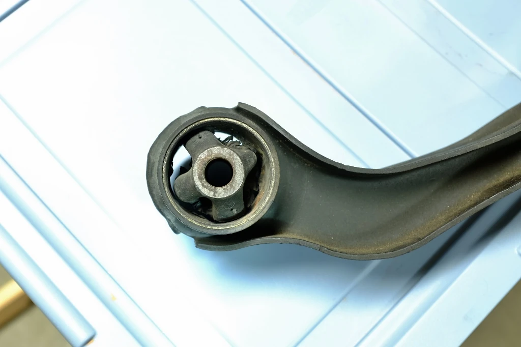
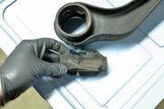
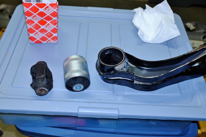
The rubber part vaguely resembles an airplane. The nose and the tail are not bonded to the inner surface of the bushing. They act as limit stops for the to-and-fro motion of the bottom of the power plant. The tips of the wings are bonded to the bushing.

In this mount, the tips of the wings are broken right off.

This shows the new Pendulum Mount installed.
Instead of replacing the Pendulum Mount arm and all, another approach would be to acquire just the bushing part, which is VW part number 701 399 207b or Febi Bilstein 37099 and finding a machine shop that can insert the new bushing. The 'whole arm' part shown here is a VAICO V10-0881 which was obtained retail from Europarts-SD. If you want the bushing only, it appears these are available from Ebay sellers based overseas. It is unknown whether the VW part (bushing only) can be ordered from a US dealer's parts department.


Transmission bushing[]
How to extract the old bushing and install a new one with the transmission still in the vehicle is <to be determined>.

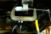
This approach might work for extracting the transmission bushing. On this project, however, the extraction was aborted.
- Cooling System Bleeder Screw
- Radiator fan strip fuses
- Serpentine belt
- Fuel Pump
- Cruise Control Module
- Mass Air Flow Sensor
- Heater Hose Tee
- Front Brakes
- Front windshield washer nozzle grommets
- Fuel Filter
- Sliding Window Latch Repair
- EVC poptop
- Cruise Control Brake Switch
- Sliding door
- Heater Flaps
- Final Drive or Differential
- Roof Vent Putty
- Secondary Air Injection pump strip fuse
- EVC luggage rack